Your boss has no faith in the the idiots in the electronics design division and is concerned that there will be a time delay of up to 0.1 second when the electronic circuitry does
the necessary
computations for D(s). The block diagram for the delayed system is
illustrated as follows:
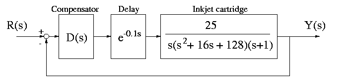
Using a second order Pade approximation of the time delay, plot a root
locus plot of the delayed system using proportional control.
Using a root locus plot, determine the approximate maximum value for K
for which the closed loop system is stable.
Enter the value you determined here: K = . (15 points)
Ignore time delays for the rest of the exam!
Referring to the first block diagram, in order to achieve crisp printing characteristics, it is desired that
the following specifications be achieved:
- rise time: tr < 0.4 seconds;
- maximum overshoot: Mp < 20%
- steady state error for a ramp input: ess < 1/80.
- Where should the dominant closed-loop second order poles be located to achieve the
desired transient response?
Enter the value you determined here: s =
(enter something of the form "1 + 2 i"). (5 points)
- Referring to your root locus plot from Problem 1a, can this response
be obtained using proportional control only?
Yes or no: . (5 points)
Regardless of whether you answered yes or no to the previous question,
your boss tells you to design a lead/lag controller to attempt to meet
the specifications.
- If the zero for the lead controller is placed at s = -3,
where (approximately) should
the pole for the lead controller be placed to achieve the desired
response?
Enter the value you determined here: p = . (10 points)
- What is the value of the gain, K which corresponds to the
desired pole locations when the lead compensator is used?
Enter the value you determined here:
K = . (5 points)
- Submit a plot of the response of the system to a step input to verify
the properties of the lead controller. If there are any discrepancies, attempt to
explain them here:
(5 points)
- Now design a lag controller to reduce the steady state error to the desired value of 1/80 to a ramp input. If the pole of
the lag controller is placed at s = -0.01, where should the zero be
placed?
Enter the value you determined here: z = . (10 points)
- What are the gain and phase margins of the compensated system?
PM = degrees. (5 points)
GM = dB. (5 points)