University of Notre Dame
Aerospace and Mechanical Engineering
ME 469: Introduction to Robotics
Homework 4
B. Goodwine
Fall, 1998 |
Issued: October 5, 1998
Due: October 9, 1998 |
Unless otherwise indicated, all the problems are from the
course text, Craig, Introduction to Robotics. Unless
otherwise indicated, each problem is worth 10 points.
- Each project group must turn in a summary of the work
accomplished to date on Project
2. Attach this to the homework for only one
group member -- everyone will get the same credit.
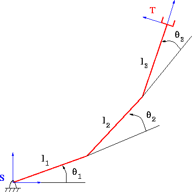
- For the three link planar robot illustrated in in the
Figure,
- determine the forward kinematics from the base frame,
S, to the tool frame T including the orientation of the
tool frame (in class, I only did (x,y));
- compute the Jacobian;
- determine at least two singular configurations; and,
- modify the animation code presented in
class to drive the mechanism from the starting
configuration given in the code along a desired trajectory
that takes it near one of the workspace interior
singularities. Verify that large joint velocities occur
near the singularity.

- In class, singularities were presented as a generally bad
thing since very large joint velocities were required near
them. However, they are good in the sense that they maximize
mechanical advantage. Show this for the mechanism in the
previous problem by finding a large force (and/or torque) near one
of the singular configurations that requires very small joint
torques to maintain.
- In Homework 2, you determined the forward kinematics for
the mechanism in problem 3.18, Figure 3.38. Assume that we
are interested in the (x,y,z) location of the end
effector (note that you will have to add a frame at the
end effector -- before your forward kinematic computations
only went to the frame attached to the last link at the axis
of rotation). Assume the reference configuration is as
illustrated in the figure in the book.
- Compute the Jacobian for this system;
- determine at least one singular configuration; and,
- if each joint angle is 30o, and a force, F =
(25,25,25) is applied at the origin of the end effector
frame, what are the joint torques required to maintain the
force?
- In Homework 2, you determined the forward kinematics for
the mechanism in problem 3.20, Figure 3.40. Assume that we are
interested in the (x,y,z) location of the end effector.
Assume the reference configuration is as illustrated in the
figure in the book.
- compute the Jacobian for this system;
- determine at least one singular configuration; and
- if each joint angle is 30o, and a force, F =
(25,25,25) is applied at the origin of the end effector
frame, what are the joint torques required to maintain the
force?
- In Homework 3, you determined the forward kinematics for
the mechanism in problem 3.21, Figure 3.41. Assume that we are
interested in the (x,y,z) location of the end effector.
Assume the reference configuration is as illustrated in the
figure in the book. What are the singular configurations for
this mechanism?
- (Wait until afer Wednesday's class to attempt this
one).
Consider the four dimensional SCARA type robot considered in
class last week. Assume that each of the three rotational
joints is at
30o, and the prismatic joint is at the reference
configuration, i.e., theta_4 = 0.
- What is the direction of the maximum mechanical
advantage?
- What is the direction of the maximum velocity amplitude?
Last updated: October 5, 1998.
B. Goodwine (jgoodwin@nd.edu)
