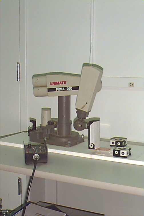
It is now 2003 and you are working for a company that fabricates parts for the aerospace industry. All the parts that are produced need to be sprayed with a special coating that inhibits material degradation. In the past, your company has used a PUMA 260 equipped with a spray nozzle to coat the parts and they have used the teach-repeat method to program the robot. While extremely precise motion is not necessary, the robot does have to maintain about .25 inch precision in its motion in order to evenly coat the part that it is spraying.
Recently, your company has received many orders for small batches of parts. Since teach-repeat is tedious and the most boring part of your job, you have decided that instead of having to reprogram the robot every time a new part is fabricated, you will write a computer program that will automatically program the robot's trajectory for a given part.
The way you decided to do this is as follows. The CAD drawings and files are available for every part that is made. You can write a computer program that parses the CAD file to determine the shape of the part, and using that information, the computer program will output a VAL program that, when transferred to the robot via the GUI, will make it follow the correct trajectory. Basically, you are going to write a computer program that takes the output from another program (the saved CAD file) and writes another computer program (the VAL) that will be used by the robot.
Your boss is enthusiastic about your proposal because it will be cheaper and more efficient than the current need to always teach the robot a new trajectory every time a new part is designed, and has asked you to demonstrate its feasibility.
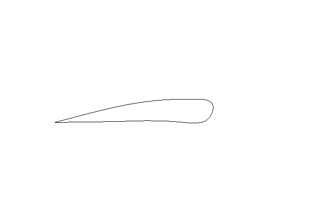
The CAD file format that the design engineers use is called DXF, which stands for Document eXchange Format. CAD programs, such as autocad can export files in DXF format. ProE can as well, but not the student version. Autodesk, the maker of autocad, has the specification for DXF files available on line. It may be a good idea to skim most of it, but you will want to pay particular attention to the ENTITY called POINT. A sample DXF file that is a drawing of the cross section of an airfoil that you can use to help write your program has been furnished by the design team.
The part designers may use a variety of elements to define a part, but they always define a series of points (encoded in a DXF file by the "POINT" keyword) around the perimeter of the part. If the robot can have the spray nozzle follow close to those points with the correct orientation, it will follow the correct path to treat the part. If your program can read the points from the DXF file, it can then use them to do the necessary computations to create a VAL program.
To help you get started, for a huge consulting fee, one of your former professors wrote a C program that parses a different DXF file to look for the words "RADIUS," "ANGLE" and "STEPS" and to then read a radius, angle and number of steps which are numbers in the DXF file that appear on the line following the keywords. The same program creates a VAL program that causes the PUMA 260 to move in a circular arc of the radius, through the angle specified where the arc is approximated by the number of straight line segments that are specified by the line following STEPS. This program can be transferred to the PUMA via the GUI.
Since "time is money" your boss does not want any sort of written report describing what you did. All that is required is that you submit your code and demonstrate that the program works by:
Since a huge number of new part orders is arriving soon, this program must be running by April 4, 2001.
You are encouraged to program the robot using any of the VAL commands that you wish, but most likely you will use some of the following:
     MOVE, MOVET, MOVES or MOVEST
     DRAW
     APPRO or APPROS
     DEPART or DEPARTS
     HERE
     SPEED
See Chapters 4 and 5 of the Programming manual (in the lab
near the Puma) for details of
each of these commands. Feel free to use other commands as well.
You may also wish to consult Chapter 6 of the Programming
manual for an example program.
The computer communicates with the robot through its serial port. To establish communication with the robot, start a terminal emulation program, such as
minicom
The terminal must be configured with the following transfer protocol:
    baud: 9600
    parity: none
    stop bits: 1
    bits: 8
    device: /dev/ttyS0
Minicom should have these for the default settings; however, if you do have to change them, hit
control-a z
to pull up a menu. From there you can set the transfer protocol.
See the man pages for each program or ask the instructor for more
details (in that order).
To exit minicom, type
control-a x
Important:
LIMPcommand; and,
SPEED 10
SPEED 10 ALWAYSAfter a program is completely debugged, you can set the speed higher, but never more than 50.
puma
at the prompt on the computer. Unfortunately, the GUI is not
completely debugged, so occasionally things may go awry.
Important: do not turn on the robot until the GUI tells you to.
To download a program to the robot controller using the GUI, under the "Program" menu you will find "Transfer" which allows you to download a program from the PC to the robot controller.
Under the same menu, you will find "Execute" which executes the program that is downloaded. This lab description is intentionally incomplete. To get the robot to even move at all, at least one member of the group will have to study the instruction manuals for the robot before you attempt to program the robot to complete the project. Where appropriate, this project summary indicates which chapters in which manual are relevant. Using the
HERE point_name
command, (where point_name is something like "p1" "p2" etc.) you will be able to name or define the various points,
which then could be used in a program with the
MOVE point_name
command to have the robot automatically go through the sequence of
steps necessary to swap the pallets. The program must start and
end in the "ready" position.
Hint: sections 2-4 and 2-5 of the Programming Manual contain an example program which will be very helpful. Also, near those sections is a description of how to use the editor used to program the robot.
Hint: there are "program commands" and "monitor commands." To execute a program command directly from the terminal, prepend the command with "DO," e.g.
DO MOVE POINT2
will make the robot move to POINT2. You cannot just type "MOVE
POINT2."
Use the command
EXECUTE program_name
to execute the program. To run a program repeatedly, use the
command
EXECUTE program_name,n
where n is the number of times you want it to repeat.
To stop an executing program, type
ABORT
and the robot will stop at the end of the current command.
All the commands are the same for the GUI except the addition of one more command, which allows you to numerically define points. The new command is
DP
and its use is illustrated in a sample program.
Return to the AME 469 Homepage.