A micro-controller communicates with the outside world by either
Recall that the IO pins of the Motorola 68HC11
micro-controller IC are arranged into four 8-bit ports.
Each of these ports is directly connected to a hardware
register that is memory mapped into RAM address space. As
a result all IO ports are memory mapped. The actual
addresses for these IO ports are associated with logical
names such as PORTA, PORTB, PORTC, and PORTD. If you take
a look at the hc11.h include file that is input as
part of kernel.c, you'll see the following
declarations of the form
#define PORTA *(unsigned char volatile *)(_IO_BASE+0x00)This declaration associates the logical name
PORTA
with the physical address _IO_BASE+0x00. In the
MicroStamp11, _IO_BASE has the value 0x00.
These ports serve as either inputs or outputs for the micro-controller (hence the name IO port). At a given time, however, a pin can only act as either input or output. This means that each pin has a distinct direction state. A pin cannot be used for input and output at the same time. In other words, the directional states input and output are mutually exclusive. In other words, once you've decided to output a voltage on pin 3 of PORTA, you cannot go ahead and try to read that voltage. You must actually reset the direction state of that pin before attempting to read the pin's logical state.
We can think of each pin on an IO port as a single bit in an 8-bit binary number. If PORTA is in its output state, then setting a bit in PORTA high, gives it the logical value 1. Because this bit is directly mapped to the IO pin, then setting a bit in PORTA high causes the voltage on the associated pin to +5 volts. Setting a bit low in PORTA gives that bit the logical value of zero and causes the output pin to be set to ground (0 volts).
As an example, let's consider the program you wrote in the MicroStamp11 familiarization learning module. In that program you used the following instruction on PORTA
PORTA = 0xFF;This instruction sets all bits of PORTA "high". PORTA is the logical name for MicroStamp11 pins 1-8 (PA7-PA0). The hex number
0xFF corresponds to the binary number
11111111, which means that all 8 bits of PORTA have
been set to one (high). As a result all pins on PORTA
whose direction state is "output", would be set to +5
volts. Similarly, if we had wanted to set all output pins
on PORTA low, we would have used the instruction
PORTA = 0x00;
The programmer can control a pin's direction state by
setting an appropriate bit in a direction register.
Direction registers are hardware registers in the 68HC11
that are also memory mapped into the device's RAM address
space. Rather than accessing the registers by their
absolute addresses, the programmer would use the addresses
logical name. These logical names are defined in
hc11.h (definitions have the same form that we saw
earlier for the IO port addresses). The logical name for
PORTD's direction register is DDRD. If the
![]() th bit in
th bit in DDRD is set high (1), then bit
PDi is treated as an output port. If the ![]() th bit
in
th bit
in DDRD is set low (0), then bit PDi is
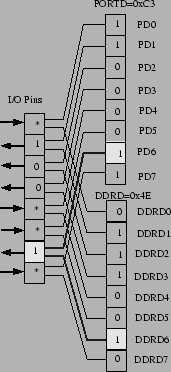
treated as an input port. Figure 14
illustrates how DDRD effects the IO directions of
PORTD. In this figure, we set DDRD to
0x4E and we set PORTD to 0xC3. The
logical values output by the physical pin is shown on the
figure as either a 1 or 0. If the IO pin has been marked
with an asterisk, then its output value is unspecified
because the pin's direction state has been set to "input".
The preceding discussion showed how to set the IO direction
state for PORTD. What about PORTA? Not all
of PORTA's IO pins are bidirectional. In fact, only
two pins (PA3 and PA7) can have their
direction states set by the programmer. The other pins on
PORTA are tied to specific timer interrupt functions that
fix the pin's direction state as either input or output.
For the pins PA3 and PA7, the programmer can
set their direction state by setting the appropriate bits
in the hardware register PACTL. In particular, the
logical names for the direction bits in PACTL are
DDRA7 and DDRA3. Bit DDRA7 sets the
direction state of pin PA7 and bit DDRA3 sets
the direction state of pin PA3.
As mentioned above, only pins PA3 and PA7 on
PORTA are bidirectional. The other pins in
PORTA have fixed directional states. In particular,
pins PA4 to PA6 are always output pins
whereas pins PA0 to PA2 are always input
pins.
You can access all of the PORTA pins on the
MicroStamp11 module. All of the PORTD pins are
bidirectional, but you can only access six of
PORTD's pins on the MicroStamp11
(PD0-PD5). This means that you have a total
of 8 bi-directional pins, 11 output pins, and 11 input pins
on the MicroStamp11.
The logical state of an input pin (high or low) can be
determined by examining the appropriate bit in the port's
logical name (PORTA or PORTD). Because the ports are
memory mapped, we don't need to waste memory cycles
fetching the port's state, we simply need to check the
value of the bits in memory. As an example, let's assume
that we want to check the logical state of pin PA1.
Since pin PA1 is always an input pin, we don't need
to explicitly set its input state. So we could check the
bit's logical state with the following code segment
 if((PORTA & 0x02) == 0){
   OutString("PA1=Low");
 }else{
   OutString("PA1=High");
 }
The conditional test takes the logical-and of PORTA
and the binary number 0x02. The result of the
"and" operation is to produce one of two numbers. The
result is 0x00 if the second bit in PORTA is low
or we get 0x02 if the second bit in PORTA is high.
Note that if we had wanted to check the logical state of
pin PA3, we would first need to set the pins
direction state to input before attempting the test the
bit. In other words, we would need to use the code
segment
   PACTL |= DDRA3;
   if((PORTA & 0x08)==0){
     OutString("PA3=Low");
   }else{
     OutString("PA3=High");
   {
Note that we set the DDRA3 bit in PACTL using the
incremental-or operation |=. This instruction, of
course, is equivalent to PACTL = PACTL | DDRA3.
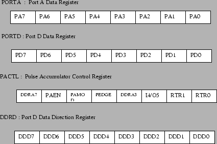
To conclude our discussion of the IO ports of the MicroStamp11, we now illustrate the hardware registers used in controlling the direction state of the IO ports. These registers along with the logical names of their bits will be found in figure 15.