The BPI-216 LCD module combines a serial (SCI) interface with a 2-line by 16-character liquid crystal display (LCD). The combination receives serial data at 2400 or 9600 baud (switch selectable) and displays it on the LCD.
The module has two modes: text and instruction. The default mode is text mode. In text mode, any received data appears on the LCD screen. You can place the module in "instruction" model by sending the instruction prefix (ASCII 254). The byte immediately following this prefix is treated as an instruction. The list of LCD instructions is given in the following table.
| Instruction/Action | Code |
| Clear Screen | 1 |
| Scroll display one character left (all lines) | 24 |
| Scroll display one character right (all lines) | 28 |
| Home (move cursor to top/left character position) | 2 |
| Move cursor one character left | 16 |
| Move cursor one character right | 20 |
| Turn on visible underline cursor | 14 |
| Turn on visible blinking-block cursor | 13 |
| Make cursor invisible | 12 |
| Blank the display (without clearing) | 8 |
| Restore the display (with cursor hidden) | 12 |
| Set cursor position (DDRAM address) | 128+addr |
| Set pointer in character-generator (CG) RAM | 65+add4 |
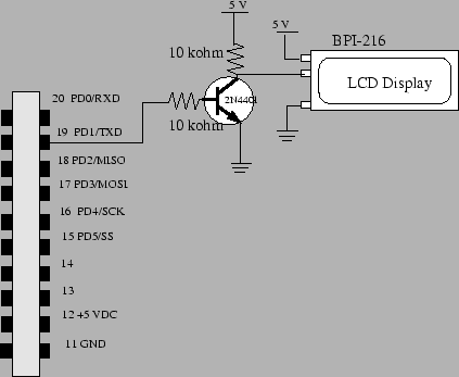
The connections between the BPI-216 module and the MicroStamp11 are relatively simple. There are three important wires coming out of the module. The red wire is tied to the positive supply voltage (+5V). The black wire is tied to ground and the white wire is the serial input line. You cannot, however, directly connect this serial line to the MicroStamp11's output. This is because the unit expect an inverted TTL/CMOS logic signal whereas the MicroStamp11 produces a positive TTL logic signal. So you will need to invert the signal between the MicroStamp11 and the BPI-216. This is accomplished using the simple circuit shown in figure 27. This circuit accepts a 0 or 5 volts input and outputs a 5 or 0 volt signal, respectively.
The following C-language program writes to the LCD display.
In this example, we've modified the init() function
so it transmits at 9600 baud using the instruction
BAUD = BAUD9600;The following main program writes out the lines
 S= 8 0001000
 R= 7 1110000
to the LCD display.
void main(void){
  unsigned int ddata;
  unsigned int bdata;
  int i;

  init();
  ddata=8;
  bdata=7;

  while(1){
    OutChar(254);OutChar(2);  //go home
    OutString("S=");
    OutUDec(ddata);OutChar(SP);
    for(i=0;i<8;i++){
      if((ddata & bit(i))==0){
        OutChar('0');
      }else{
        OutChar('1');
      }
    }

    OutChar(254);OutChar(192);  //go to second line
    OutString("R=");
    OutUDec(bdata);OutChar(SP);
    for(i=0;i<8;i++){
      if((bdata & bit(i))==0){
        OutChar('0');
      }else{
        OutChar('1');
      }
    }
  }
}