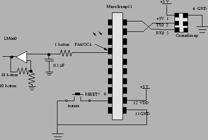
In this learning module you'll build a system that generates a PWM wave that drives the capacitive DAC we discussed earlier. You can use a Hyperterm shell to enter the duty cycle for the PWM wave. The principles behind the hardware and software for this project were discussed above. Figure 11 shows the schematic diagram for your system.
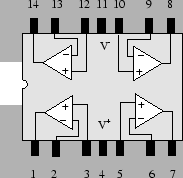
Note that this circuit uses an LM660 op-amp. The LM660 IC
has 4 operational amplifiers on it. You'll only need to
use one of them. The pinout for the device is shown in
figure 12. Note that you'll need to connect a
+15 volt supply voltage to ![]() and you'll need to
connect
and you'll need to
connect GND to ground.
The software side of this project is shown in the following listing.
 #include"kernel.c"

 void main(void){
   unsigned int duty_cycle;
   init();
   while(1){
     OutChar("enter duty cycle:");
     duty_cycle=InUDec();
     set_pwm(duty_cycle);
   }
 }
 #include"vectors.c"
This deceptively simple program does nothing more than
wait for the user to input the duty cycle for the pwm
wave. The program then uses this input value to set the
duty cycle of the pwm. Note that because the duty cycle
is always executed by the output compare interrupt, that
this periodic signal is generated on pin OC4 even
though the program is blocked in the while loop until the
user enters a new duty cycle number. This simple program
shows how interrupts such as the OC4 interrupt can be used
to make the micro-controller appear to do two things at
once. In this case, those two things are waiting for
the user to supply an input and generating the PWM signal.