The channel is the medium through which we transmit information. There are essentially two types of channels. The "wired" channel consists of media such as copper wire, co-axial cables, and fiber optic cables. The "wireless" channel consists of media such as air, water, vacuum, or earth.
When we transmitted bytes to the LCD display, the information was transmitted through a copper "wire" channel. In this case, we simply applied a voltage at one end of the wire. The receiver at the other end of the wire would detect the potential drop. In a wireless channel, information propagation is more complex. In most cases, wireless channels rely on wave dynamics to transmit energy through the medium. As an example, we might consider a channel such as a vacuum and the propagation of light across this channel. Light is an electro-magnetic (EM) wave. Essentially, this means that we have electrical and magnetic fields that pass energy back and forth between each other. The dynamics of this interaction are such that the wave propagates over a distance. Other wireless channels that rely on either acoustic (air/water) or seismic (earth) waves rely on similar dynamical mechanisms for wave propagation
A channel is not an ideal medium for energy transmission.
Channels often distort the signals that pass through
them. The channel can add "noise" to the signal. In
particular, we can think of the channel (such as air) as
a "system block". The input into the block is the
transmitter's output signal and the output of the
channel is then input into the receiver. If the channel
can be represented as a linear system, then we may
relate the channel's input  to its output,
  ,
through the following equation
,
through the following equation
Since ![]() is
network's frequency response. We can graph the
magnitude of this function (
is
network's frequency response. We can graph the
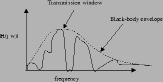
magnitude of this function (![]() )
as a function of the frequency of the
EM wave that's propagating over the channel. One
possible frequency response is shown below in figure
46. What you'll note here
is the classical black-body radiation profile with
several holes in it. The holes refer to places where
the atmosphere absorbs EM radiation. Obviously, if we
were to transmit a signal in a frequency range
covered by one of these holes, then
very little of the signal would reach the receiver. So
the transmitter usually encodes the information signal
onto a carrier wave whose frequency sits in one of the
frequency "windows" in which the atmosphere is nearly
transparent. One of these particular windows occurs in
the infra-red (IR) range of the EM spectrum, which
is why we're building an IR wireless link in this learning
module.
)
as a function of the frequency of the
EM wave that's propagating over the channel. One
possible frequency response is shown below in figure
46. What you'll note here
is the classical black-body radiation profile with
several holes in it. The holes refer to places where
the atmosphere absorbs EM radiation. Obviously, if we
were to transmit a signal in a frequency range
covered by one of these holes, then
very little of the signal would reach the receiver. So
the transmitter usually encodes the information signal
onto a carrier wave whose frequency sits in one of the
frequency "windows" in which the atmosphere is nearly
transparent. One of these particular windows occurs in
the infra-red (IR) range of the EM spectrum, which
is why we're building an IR wireless link in this learning
module.