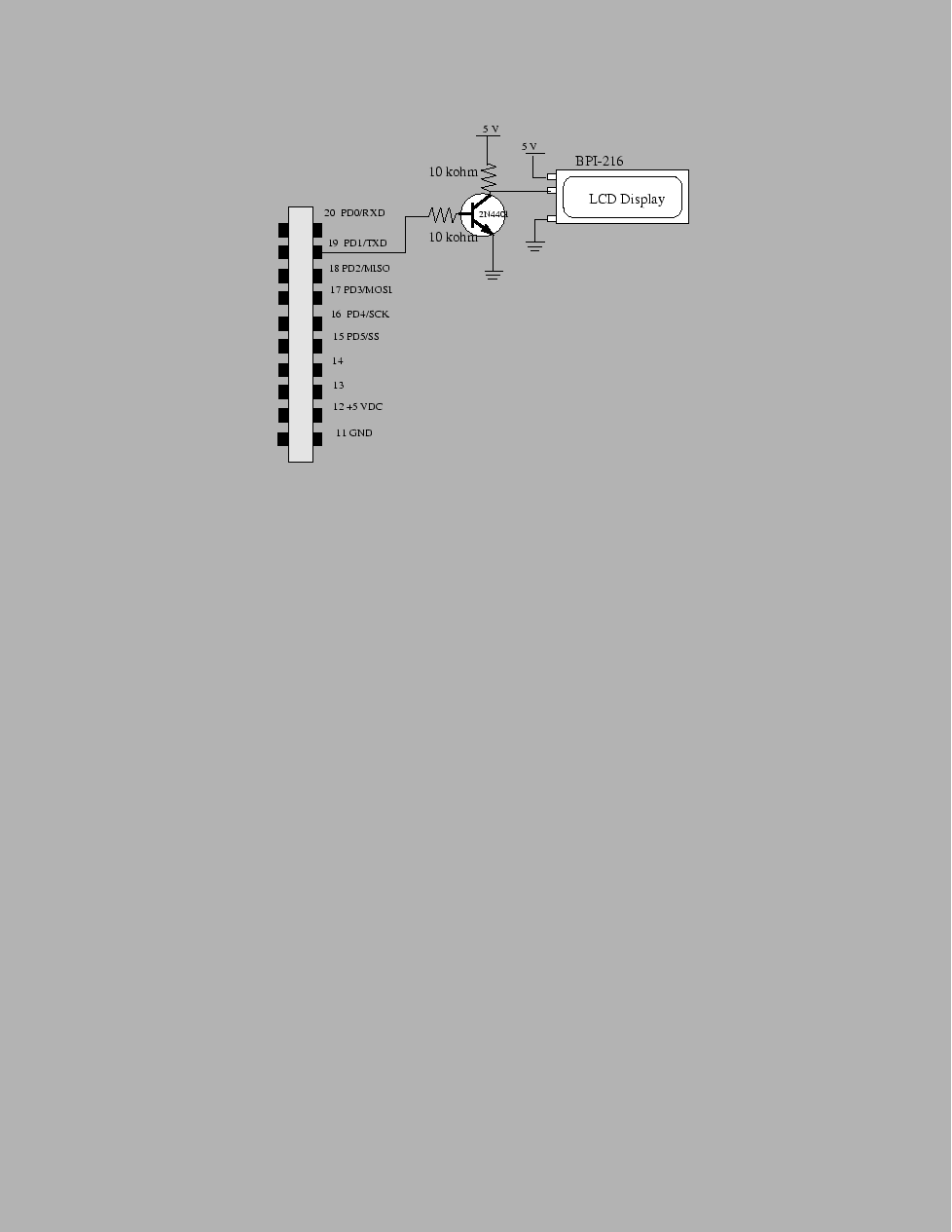
The serial communication protocols you used to communicate with the LCD display transmitted a series of voltage pulses down a wire. Each pulse represented a bit. When you attached an oscilloscope to this wire and triggered correctly, then the observed trace might have looked something like the trace in figure 44.
There are, however, other ways of transmitting information besides toggling between zero and 5 volts on a single wire. We can abstract the serial communication system to obtain a block diagram something like that found in figure 45. In this figure, we find an information source, whose information is transformed into a signal that can be transmitted through a physical channel. On the other end of the channel, the received signal is transformed back into information that can be directly used by the destination.
The block diagram shown in figure 45 represents a high level abstraction of a concrete communication system. But given this abstraction, we can substitute our preceding realization for these blocks by other concrete realizations and thereby obtain a different type of communication system. The different type of communication system we'll consider in this learning module is a wireless communication system. We now discuss each part (the channel, transmitter, and receiver) of this wireless system in a little more detail.