The MicroStamp11 is a micro-computer and you will need to load a program into its EEPROM before it does anything. Loading such a program raises the obvious question; how do you the programmer communicate with the MicroStamp11? Unlike your personal computer, the MicroStamp11 does not have a keyboard or terminal associated with it. The MicroStamp11 is an embedded system that is designed to talk to other electronic circuits. It was designed to directly talk with a human user. Therefore, if you, the human user, wish to talk to the MicroStamp11, it must be done through an intermediary. That intermediary is your personal computer. Your personal computer can communicate with the MicroStamp11 through its serial port. The human user communicates with the serial port through a terminal program such as Hyperterm. You can locate the serial port on the back of your PC by its distinctive 9-pin D shaped connector (also called a DB9 connector). The module has a DB9 null modem cable in it. You will need to insert one one end of this cable into your personal computer's serial port. The other end of that cable must be connected to the MicroStamp11.
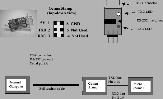
Obviously we are still missing something because there is no DB9 connector on the MicroStamp11. We need to use another module to connect the DB9 null modem cable to the MicroStamp11. This other module is the comm-stamp. The comm-stamp is a 6 pin module that has a DB9 connector on one end and it can be plugged into your protoboard. A picture and pinout for the commstamp is shown in figure 12.
The comm stamp has the DB9 connector sitting on top of the module. There are six pins that you can plug into the protoboard, but only four of the pins are actually used. Power must be supplied to the module through pin1 (VDC) and pin 6 (GND). Information is transmitted out of the module through pin 2 (TXD). This pin must be connected directly to pin 19 (TXD) on the MicroStamp11. A similar conenction between comm stamp pin 3 (RXD) and MicroStamp11 pin 20 must also be made. The comm stamp has two light emitting diodes (LED) that flash when information is being transmitted or received. The connection between your personal computer and the MicroStamp11 is graphically illustrated in the bottom drawing in figure 12. The schematic drawing showing the connections between the commstamp and the Microstamp11 will be found in figure 11. All of these connections should already have been made on the protoboard provided in the learning module. Check these connections and if they are not there, then you'll have to fix them.