Once you have power connected to the MicroStamp11, how do you start it? In other words, if there is a program already loaded into the module's EEPROM, how do we start the module executing this program?
What we want is something like the CTRL-ALT-DEL key sequence that a computer running Microsoft Windows might use to reboot the system. If you take a close look at the pinout for the MicroStamp11, you'll note that pin 9 has the label RESET. This pin is associated with a hardware interrupt that automatically causes the micro-controller's program counter to jump to the start location in EEPROM as soon as the pin is set to zero volts. After the computer jumps to the start location, it begins whatever program was stored in EEPROM.
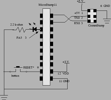
What you need to do is connect pin 9 (RESET) to ground through a push button. In this way, you can restart the micro-controller by simply pushing the button. This should already have been done for the protoboard supplied with this module.
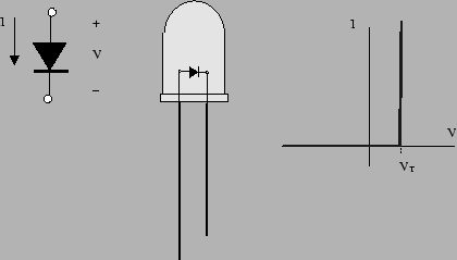
Finally, you want to connect a light-emitting diode (LED) to pin 3 (PA5). An LED is a special type of diode that emits light when it is forward biased. The symbol for a diode is shown in figure 9. The symbol looks like an arrow with a bar. This figure also defines the positive voltage and current conventions for the device. The terminal marked with a positive sign is called the anode and the terminal marked with the negative side is called the cathode.
The right-hand graph in figure 9 shows an
idealized current-voltage (IV) graph for the device. This
graph plots the current passing through the device as a
function of the voltage over the device. Note that if the
voltage is in excess of a threshold voltage ![]() , then we
say that the diode is forward biased. The current
passed by a forward biased diode can take any positive
value. If the voltage is below the threshold voltage, then
we say the diode is reverse biased. A reverse biased
diode passes zero current. In other words, a forward
biased diode acts as a short circuit and a reverse biased
diode acts as an open circuit. We may, therefore think of
a diode as an electronic valve. A light-emitting diode is
simply a diode that emits light when it is forward biased.
, then we
say that the diode is forward biased. The current
passed by a forward biased diode can take any positive
value. If the voltage is below the threshold voltage, then
we say the diode is reverse biased. A reverse biased
diode passes zero current. In other words, a forward
biased diode acts as a short circuit and a reverse biased
diode acts as an open circuit. We may, therefore think of
a diode as an electronic valve. A light-emitting diode is
simply a diode that emits light when it is forward biased.
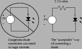
Let's assume that we connect the MicroStamp11's output pin (PA5) to ground with a diode as shown in figure 10. The output pin acts as a 5 volt voltage source when it is set high. So if this pin is high, then the LED is forward biased. A forward biased LED, however, acts as a short circuit. What we need to determine is the current flowing through this "short-circuit".
The current that the output pin would need to supply is
given by a well-known law known as Ohm's Law. Ohm's law
says that the voltage ![]() over a resistor is proportional
to the current
over a resistor is proportional
to the current ![]() passing through the device. The constant
of proportionality is called the resistance,
passing through the device. The constant
of proportionality is called the resistance, ![]() and it is
measured in units of ohms. Mathematically, we express
Ohm's law by the equation
and it is
measured in units of ohms. Mathematically, we express
Ohm's law by the equation
We can limit the LED's current by connecting it in series with a passive two-terminal device known as a resistor. The MicroStamp11 can source about 5 milli amps. To limit the current through a forward-biased LED to this level we need to connect a 1 k-ohm resistor in series with the LED. This "safe" way of connecting an LED to the MicroStamp11 is shown in figure 10.
For this learning module, the protoboard should already have the LED, reset button, and power supplies connected to the MicroStamp11. A schematic diagram for these connections will be found in figure 11. If some of these connections are missing you'll need to restore them before going on.