 |
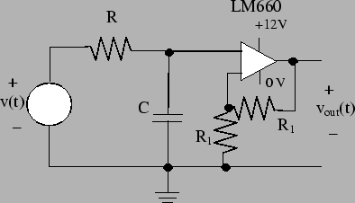
Figure 34 shows a capacitive circuit. This circuit will generate an analog voltage when the applied voltage is a PWM signal.
The circuit in figure 34 is driven by a
PWM signal, ![]() . The remainder of the circuit is
divided into two parts. The first part is the RC circuit
combination. This part transforms the PWM input signal into
an analog voltage. The second part is the op-amp circuit that
generates the output voltage
. The remainder of the circuit is
divided into two parts. The first part is the RC circuit
combination. This part transforms the PWM input signal into
an analog voltage. The second part is the op-amp circuit that
generates the output voltage
![]() . This
op-amp circuit is used to buffer the RC circuit from
any load that has been put across the circuit's output.
We will now discuss how the RC and op-amp parts of this
circuit work.
. This
op-amp circuit is used to buffer the RC circuit from
any load that has been put across the circuit's output.
We will now discuss how the RC and op-amp parts of this
circuit work.