Now let's consider the RC circuit shown in figure 35. What might we do with this analog voltage? One obvious thing to do is to use it to drive some other electronic device such as a speaker. Unfortunately, we will encounter a problem if this happens. Audio speakers have an input resistance of 8 ohms. If we were to connect an 8 ohm load across the capacitor shown in figure 35, then we would dramatically change the circuit's characteristics and this loaded circuit would no longer produce the desired output voltage. To solve this problem, we need to buffer the RC circuit from any load we might attach to the system. The easiest way to realize such a buffer is to use an op-amp.
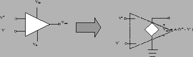
Operational amplifiers are high-gain amplifiers that
amplify the difference between a non-inverting and
inverting input terminal. The symbol for an op-amp is a
triangle that has two inputs and a single output. The
symbol is shown in figure 39. The input
with a positive sign is called the non-inverting
terminal and the input with the negative sign is called
the inverting terminal. A near infinite input
resistance, a very small output resistance, and a large
voltage gain
characterize the operational amplifier. The open
circuit output voltage, ![]() is proportional to
the difference of the voltages at the non-inverting
terminal,
is proportional to
the difference of the voltages at the non-inverting
terminal, ![]() , and at the inverting terminal
, and at the inverting terminal ![]() .
This can be expressed by the equation
.
This can be expressed by the equation
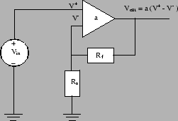
The fact that the operational amplifier has an extremely large voltage gain is extremely important aspect of this device. The reason for this importance can be seen in a special feedback circuit in which the op-amp['s output feeds back to drive its input. In particular, we'll consider a standard non-inverting connection using an op-amp. The inverting connection is shown in figure 40.
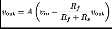
It can be shown using elementary circuit analysis, that the
output voltage ![]() is related to the input
voltage,
is related to the input
voltage, ![]() by the following equation,
by the following equation,
 |
 |
Note that the circuit shown in figure
40 is precisely the second part
of the pwm circuit shown in figure 34.
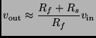
In that circuit, however, we've chosen ![]() , so that
the output voltage
, so that
the output voltage ![]() generated by the
pwm-circuit is actually twice the voltage over the
capacitor
generated by the
pwm-circuit is actually twice the voltage over the
capacitor ![]() .
.
Why did we need this circuit? Remember, that the op-amp has an extremely small output resistance. So if we were to attach a load across the terminal of the circuit, all of the voltage generated by the op-amp would drop across the load. Moreover, since the op-amp has a large input resistance (nearly infinite), connecting this op-amp circuit to the RC circuit does not lead the circuit very much. As a consequence the non-inverting op-amp circuit shown in figure 40 buffers the RC circuit from the load and we can now use our DAC system to drive some other circuit.
One other thing to note about the op-amp is that it
produces voltages that are outside of the standard TTL/CMOS
logical range of 0-5 volts. This means, however, that the
5-volt supply cannot be used to supply the op-amp. If you
look at the op-amp symbol in figure 39,
you'll note that there are two additional terminal coming
out of the op-amp. These are the two supply voltages. In
fact to get the full 0-10 volt output from this circuit,
you'll need to supply at least 12 volts to the op-amp's
positive supply terminal ![]() . You can leave the
negative supply terminal tied to ground.
. You can leave the
negative supply terminal tied to ground.